Featured Products
Introduction
Demonstrations of two-dimensional standing waves using Chladni plates are certainly impressive and can help instill a sense of awe and wonder in our students. We want to expose our students to things they can’t yet explain. We want to spark enough curiosity to get them to ask how something like this is even possible. But we don’t want to just leave them wondering. We want to give our students the conceptual tools to make sense of their observations. This is what the discipline of science is all about!
In this blog post, I will walk you through a digital resource I created to give students a conceptual understanding of “standing waves”, the phenomena behind the patterns created on this vibrating plate. All of the content is conceptual and can be used for the middle school level, up through introductory physics at the college level. This Standing Waves Digital Resource outlines the basic progression of concepts needed for students to understand what a standing wave is, and how it can be created. The Standing Waves Digital Resource includes animations, links to free simulations, suggested demonstrations, and videos that can be used in your classroom.
All the equipment used in the suggested standing wave demonstrations come from the “Mechanical Wave Complete Bundle”.
Developing the Standing Wave Concept
Step #1 (Mechanical Wave Introduction)
The first step in helping students build a conceptual understanding of standing waves involves a basic understanding of mechanical waves. Slinkies and coiled springs are a great hands-on way to introduce the basics of mechanical waves to students. Arbor Scientific has many options including their “helical spring”, “spring wave”, and “super spring”. Students can also investigate the basics of mechanical waves using an interactive simulation, like the one available from the PhET Interactive Simulations website titled “Waves on a String”.
Any introduction to mechanical waves must give students an understanding that mechanical waves are disturbances that move through a solid, liquid or gas when the material or medium is disturbed, travel outward from the initial disturbance in all available directions of the material, and a “wave” is moving energy, not moving matter. It helps to show or discuss several different examples of mechanical waves moving through solids, liquids and gasses.
I have students use the Waves on a String simulation to further investigate the properties and behavior of moving disturbances or waves. The investigation gives students an understanding of how to describe a wave’s amplitude, pulse width and speed. The investigation also introduces the concept of damping, reflected wave behavior, and the effect tension has on wave speed. You can find links to the simulation and corresponding student worksheet in the Standing Waves Digital Resource.
Through the Waves on a String activity students should be able to identify characteristics of a wave like amplitude and pulse width, recognize that the wave speed is only changed by the tension in the string, wave pulses are reflected differently off of open or fixed ends, and damping refers to a decrease in wave height or amplitude over time.
Step #2 (Periodic Waves)
Next, students need to be given a basic understanding of “periodic waves”. Students need to understand that periodic waves are created by periodic or repeated disturbances, and have a quantifiable amplitude, frequency, wavelength and wave speed.
Screenshot of animated slide in the Standing Waves Digital Resource.
The Waves on a String simulation is a great tool to introduce periodic waves because the simulation allows you to easily change the frequency of disturbance and see its effect on the periodic wave’s wavelength. The simulation can also be paused or stepped through frame by frame to show how amplitude and wavelength can be measured. At the high school and college level students need to also be introduced to the wave-speed equation showing the quantitative relationship between a periodic wave’s frequency, wavelength and speed.
Screenshot of animated slide in the Standing Waves Digital Resource.
Step #3 (Wave Interference)
Once students understand the basic properties of waves and periodic waves, the students need to be introduced to how waves interact. If you have two waves moving in opposite directions through the same slinky or string, what happens when they meet? Is it like two cars that collide in a head-on collision? Do the waves collide and stop? Do the waves bounce off each other? Does anything change about each wave pulse after they interact?
Even with careful observation, the results of wave interactions are very difficult to observe using slinkies or strings, unless you are using high speed video. For this reason it is again helpful to use the Waves on a String simulation to investigate how waves interact. Use the simulation to create different scenarios where two pulses meet while traveling in opposite directions. It is helpful to show the students examples of pulses with different widths, and examples where the pulses meet on the same side of the string and opposite sides.
The standing waves digital resource has four different scenarios that will help students draw conclusions about how waves interact (see below). You want students to see that the two waves pass through each other unaffected by the interaction. Each wave looks the same and is traveling in the same direction, at the same speed as it was before the interaction. The really interesting thing happens when the two waves are in the same location at the same time. Remind students that the string can only do one thing. The string can’t be in two locations at the same time. The result of the wave interaction is known as wave interference or superposition. When the pulses are on the same side of the string there is “constructive interference” where the total displacement of the string in the area of overlap is LARGER than it would be due to either of the individual pulses or waves. When the pulses are on the opposite side of the string there is “destructive interference” where the total displacement of the string in the area of overlap is SMALLER than it would be due to either of the individual pulses or waves.
Screenshot of animated slide in the Standing Waves Digital Resource.
It’s worth pausing here just to highlight how big of a difference there is between how waves interact compared to how objects made from matter interact. When two cars collide, they push on each other, and their speeds will change, and either both or one could change its direction of travel. If two cars interacted like waves, they would pass through one another without changing speed, and where they overlap, the part of the car at that location would either be bigger or smaller than either of the two individual cars.
Step #4 (Interference of Periodic Waves)
Now that students understand how two individual wave pulses interact, you can help students think about how two periodic waves would interact when passing through each other in the same material, moving in opposite directions.
Screenshot of animated slide in the Standing Waves Digital Resource.
We know the periodic waves will pass through each other, unchanged in wavelength, amplitude and wave speed, but what about the material the waves are traveling through? Each part of the material will be equal to the sum of the individual waves moving through that location at that specific time. There will either be constructive or destructive interference happening at each location along the length of the material. It gets really complicated to think this through without using an animation. The Standing Waves Digital Resource includes animations to help students visualize how two periodic waves interfere with each other while moving through the same material.
Imagine we have two students shaking each end of a slinky or string, each creating periodic waves that will pass through each other. The red and blue lines represent the individual periodic waves, but remember, each part of the material can only be in one place at one time. The purple line shows the sum of the red and blue periodic waves at each point along the length of the material. The purple line represents the actual behavior of the material. There are locations that do not move from equilibrium, and other locations that are being displaced farther from equilibrium than the amplitude of either periodic wave. These locations along the material’s length do not change position over time. They appear to stand still. This is why this behavior is called a “standing wave”, and it is created by two periodic waves moving through the same material in opposite directions.
Screenshot of animated slide in the Standing Waves Digital Resource.
Highlight several locations along the material and have students try to explain why it behaves that way. The locations along the material’s length that stay at equilibrium are known as “nodes''. These are locations of complete destructive interference between the two period waves. Every time a crest from one periodic wave passes through that location, a trough from the other periodic wave cancels it out, and vice-versa. The locations along the material’s length that have the largest displacement from equilibrium are known as “antinodes”. This is a result of maximum constructive interference between the two periodic waves. Maximum constructive interference happens at locations where the crests from each periodic wave meet, or the troughs from each periodic wave meet. This is a good time to help students see the connection between the wavelength of the periodic waves moving through the material, and the distance between the nodes or antinodes. The animation should help students see that the distance between nodes is equal to one half of the wavelength of the periodic waves moving through the material.
Screenshot of animated slide in the Standing Waves Digital Resource.
Martin Kirby, another physics teacher, has created a great simulation for students to explore the interference patterns created by many different periodic waves called “Wave Add”. There is a link for this simulation included in the Standing Waves Digital Resource. One last thing to note is that a standing wave can be created with only one source of periodic disturbances. As already discussed, standing waves are created by two periodic waves moving through the same material in opposite directions, but the second source of periodic waves could just be the reflected waves from a fixed end. An animation from Dr. Dan Russell from Penn State University illustrates this really well.
Step #5 (Standing Waves in Strings)
Now you’re ready to show students some demonstrations of standing waves to help them further investigate the phenomena. Use the Mechanical Wave Driver and Sine Wave Generator to attempt to create standing waves on a stretched string. Start with a low frequency and gradually increase the frequency until the first standing wave is created. Have students count the number of nodes and antinodes in the first standing wave and determine how much of a wavelength fits in the length of the string. For the first possible standing wave, half of a wavelength fits in the string’s length since each end was a node and there was a single antinode in the middle.
Now gradually increase the frequency until the next possible standing wave is found, and have students count the number of nodes and antinodes. Again, ask the students how much of a wavelength fits in the length of the string. The students will quickly identify a pattern: standing waves are created in a string with two fixed ends ONLY when the string’s length is equal to one half the periodic wave’s wavelength, or two halves of a wavelength, or three halves of a wavelength, etc… So the Mechanical Wave Driver will only create a standing wave if the driving frequency creates periodic waves with certain wavelengths.
Screenshot of animated slide in the Standing Waves Digital Resource.
You can use the animations in the Standing Waves Digital Resource to show the first four possible standing waves for a string with two fixed ends. Even though the oscillator attached to one end of the string is moving up and down, it is effectively a fixed end since its displacement from equilibrium is small relative to the displacement of the standing wave at the antinodes. If you know the length of the string, you can then calculate the specific wavelengths that would create each specific standing wave, and at the high school and college levels you could then use the wave-speed equation to calculate the driving frequencies needed to generate those required wavelengths.
Step #6 (More Standing Wave Demonstrations)
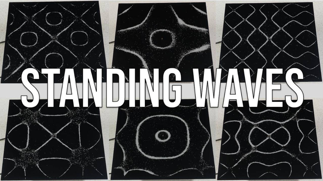
The Mechanical Wave Complete Bundle has ways to demonstrate other types of standing waves including metal strips with one fixed end and one free end, longitudinal standing waves in stretched springs, circular standing waves, and of course two-dimensional standing waves using the included Chladni Plates.
Now when students see the patterns of sand on the vibrating metal plate, they are ready to understand what creates those patterns. Just like a stretched string, only specific frequencies of disturbance will create standing waves in the metal surface. If standing waves are created in the two-dimensional surface, there should be antinodes, locations in the material that are displaced up and down more than the displacement of the Mechanical Wave Driver. These would be locations of maximum constructive interference where crests are overlapping with other crests, and troughs are overlapping with other troughs. When a standing wave is present the salt will move away from these antinode locations to parts of the material with less up and down displacement, like the node locations. There is no up and down displacement at the node locations because there is complete destructive interference between the periodic waves moving through the material. So when a standing wave is present at a particular frequency, the sand will move away from antinodes and settle at the nodes.
The complexity of the standing wave patterns increase, as you increase the frequency of the Mechanical Wave Driver. This is due to the fact that a higher frequency creates smaller wavelengths and the resulting standing waves will have higher numbers of both nodes and antinodes.
I hope this article has helped give you an idea of what it could look like to help your students understand the basics of standing waves. Remember to check out the animations, simulations and related videos in the Standing Waves Digital Resource.
Aaron Debbink
Physics Instructor
Indian Hill High School
Cincinnati, OH
Aaron Debbink is a physics teacher with 16 years of classroom experience who has an undergraduate engineering degree and a masters degree in physics. He is passionate about building a classroom culture that values exploration and a drive for understanding. Aaron uses Modeling Instruction in his introductory and AP physics classes and has been a Modeling Instruction workshop leader since 2011. Aaron is a Knowles Teaching Fellow and the recipient of a 2019 Yale Educator Award.


